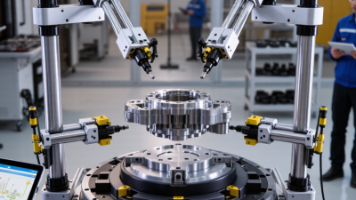
2026 Best Comprehensive Checking Fixture for Global Buyers?
A Comprehensive Checking Fixture is more than a locating tool. It helps buyers verify dimensions, alignment, and assembly conditions before defects move downstream. In 2026, global buyers must compare repeatability, inspection speed, operator usability, and support across sites. A fixture that works well on one production line may not suit another. Small details matter.
The investment also reflects a wider manufacturing shift. Deloitte’s 2019 Smart Factory study surveyed 500 manufacturing executives; 86% expected smart factory solutions to become major drivers of competitiveness within five years. That finding is not fixture-specific, but it highlights why inspection equipment should fit broader quality and production systems. Buyers should ask how a fixture handles datum strategy, tolerance requirements, calibration records, and changes between product variants. They should also confirm that drawings, materials, and acceptance criteria are clearly documented. ISO 10360 provides relevant acceptance and reverification standards for coordinate measuring systems, though it does not certify every checking fixture. Fit matters. A polished design can still create inconsistent results if clamping forces, probe access, or operator instructions are overlooked. That is easy to miss. This guide compares practical selection factors for global sourcing, including construction, measurement capability, customization, supplier communication, and lifecycle support. Some specifications will depend on the application; there is no universal best fixture. Buyers should validate critical requirements with sample parts and documented inspection plans before committing.

Define a Checking Fixture Through ASME Y14.5 Datum and GD&T Requirements
2026 Best Comprehensive Checking Fixture for Global Buyers?
Define a Checking Fixture Through ASME Y14.5 Datum and GD&T Requirements
A checking fixture is more than a shaped nest for holding a part. It should reproduce the datum reference frame defined on the engineering drawing. Under ASME Y14.5, datum features establish the references used to evaluate geometric tolerances. The fixture’s locating pins, pads, and stops must contact the intended features in the correct sequence.
Small details matter. A primary datum may need broad, stable contact, while secondary and tertiary locators constrain remaining movement. Clamps should hold the part without distorting it. Too much force can shift a thin panel and produce misleading readings. That is easy to overlook.
The fixture design should also reflect the specified GD&T controls, such as position, profile, or orientation. For example, a bore pattern may need inspection relative to the drawing’s datum structure, not simply to the fixture’s most convenient edge. Verify repeatability with representative parts and document the inspection method. A fixture can look precise and still measure the wrong relationship. I have seen teams focus on locator accuracy while leaving clamp sequence unclear; that gap deserves a second look. Part variation, access for probes, and calibration intervals should be considered before release.
Plan Part Location with the 3-2-1 Constraint Principle
A reliable checking fixture begins with a clear plan for where the part rests. The 3-2-1 constraint principle provides a practical framework. Three contact points define the primary plane, controlling motion normal to it and rotation around two axes. Two locators establish a secondary reference and restrict another translation and rotation. One final locator controls the remaining translation. The part should be located, not forced into position.
Consider a machined aluminum housing with a broad base, a side wall, and a drilled end face. Rest its base on three clean pads, then locate the side wall against two stops. A pin at the end face completes the locating scheme. Place clamps above supported areas, applying only enough force to keep the housing seated. Excess force can distort thin walls and create misleading inspection readings.
Small details matter. Chips under a pad can tilt the part, while a burr may prevent a locator from making full contact. In practice, the ideal layout is not always tidy; cast surfaces and existing features may limit locator placement. Record the chosen datums, check repeatability across several loadings, and review any unexpected movement before changing the fixture. A quick hand check helps, but it cannot replace measured validation.
Set Inspection Targets from Drawing Tolerances and ISO 1101 Symbols
A comprehensive checking fixture should translate drawing tolerances into repeatable, observable checks. Start with the datum reference frame, not just the part’s nominal dimensions. A flatness symbol controls a surface without referencing a datum, while position tolerances depend on specified datum features. These differences affect how the part must sit and how the fixture locates it.
Check the drawing’s ISO 1101 symbols and tolerance values before choosing locators, stops, or inspection points. For a hole pattern, for example, the fixture should establish the stated datums and allow the hole locations to be checked against their tolerance zones. Use stable contact points, and keep clamps from bending thin sheet metal. Small details matter. A clamp can hide a real deviation.
Set acceptance targets from the drawing, then confirm that the measurement method can resolve the required tolerance. A dial indicator, probe, or dedicated pin may suit different features, but each needs a defined contact point and inspection sequence. Record the fixture’s setup and verification results so another operator can repeat the check. One judgment call remains: unclear datum schemes may leave room for interpretation. Flag that uncertainty and seek clarification rather than quietly inventing a target.
Assess Measurement Systems Using AIAG MSA’s 10% and 30% GR&R Limits
A comprehensive checking fixture is only useful when its measurements are dependable. AIAG MSA guidance commonly treats GR&R below 10% as acceptable, 10% to 30% as conditional, and above 30% as generally unacceptable. These are decision guides, not universal guarantees. The right conclusion depends on measurement purpose, risk, and customer requirements.
Test the fixture with representative parts, trained operators, and repeated measurements. Include realistic variation: a slightly rough edge, a part seated off-center, or a clamp tightened differently. Small details matter. Review repeatability, operator-to-operator reproducibility, and the study method. Report whether %GR&R is calculated against study variation or tolerance; the denominator changes what the percentage means. A result below 10% can still mislead if the sample fails to reflect actual production.
For results between 10% and 30%, document why the system is usable and where extra inspection may be needed. Check locating pins, contact points, and clamping force before adjusting the fixture. Then repeat the study. Imperfectly, teams sometimes accept a borderline result because production is waiting. That pressure is understandable, but it should be recorded—not mistaken for measurement evidence. A clear MSA report helps global buyers compare fixtures using the same assumptions.
Verify Global Metrology Readiness Against ISO 10360 CMM Tests
For global buyers, a comprehensive checking fixture should support reliable measurement across different sites and operators. ISO 10360 provides tests for coordinate measuring machine (CMM) performance, not a certificate for the fixture itself. The distinction matters. A CMM may pass its verification while a poorly seated part still produces inconsistent results.
Assess the fixture in its intended measurement setup. Check locating repeatability, clamping force, probe access, and clearance around critical features. Record the datum scheme and the temperature conditions used during evaluation. Where practical, compare repeated measurements after removing and reinstalling the part. A small shift can expose a weak locating point. Results should be reviewed with the CMM’s applicable ISO 10360 test status and the measurement plan. One detail is easy to miss: shipping, wear, or operator handling may change how a fixture seats.
Tips: Use a stable reference part and document its orientation. Keep clamping pressure consistent. Ask suppliers for inspection records, setup instructions, and maintenance guidance. If results vary, investigate the cause before changing the measurement limits. The fixture may be sound, but the method may not be. That uncertainty deserves a second check.
2026 CMM Fixture Readiness: ISO 10360-2 Verification
Illustrative example of a declared length-measurement error limit across nominal test lengths. Values are calculated from the example equation E₀,MPE = (1.7 + L/333) μm, with L in millimetres; this is not a universal ISO limit or measured test result.
For global readiness, confirm that the fixture and calibrated test lengths suit the CMM’s measuring volume, then verify results against the machine’s declared specification. ISO 10360-2 evaluates CMM length-measurement performance; it does not define one universal pass limit for every machine.